


Process:
Wet layup
Time table:
Complete in 2 weeks
The chassis molds began from this pile of foam.
Roof bulkhead half mold.
Rear pillar mold.
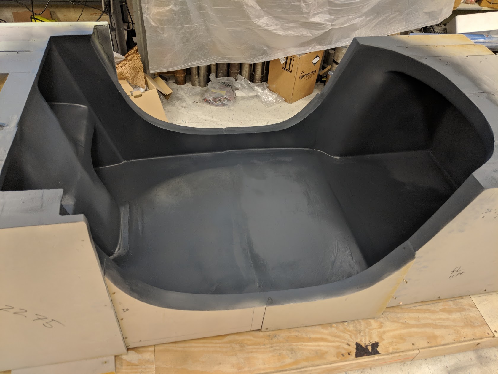
Complete chassis mold assembly with separate sub assemblies.
My twin Robert Mauge sitting in the chassis that was designed around his 3D scanned body, demonstrating how much room there is.
The decision was made to produce the chassis and the roof separately due to a 1cm discrepancy between the alignment of the front roof pillars in relation to their connection point on the chassis.
To fix the misalignment between the roof and the lower tub, the roof was infused beforehand using only 2 layers of carbon fiber so the roof could be bent into place, secured and strengthened using wet layup over the roof and chassis tub seam.
The initial plan was to use VARTM to manufacture the lower tub of the chassis. This picture shows the system of resin inlets and vacuum outlets to be used.
Resin inlets and vacuum outlets being secured to the walls of the hollow rear pillars.
Team members stretching the vacuum bag in the rear section of the mold using brooms to try and straighten the vacuum bag in the chassis pillars. We were able to create a vacuum, but it was not enough to pull resin through the entire mold.
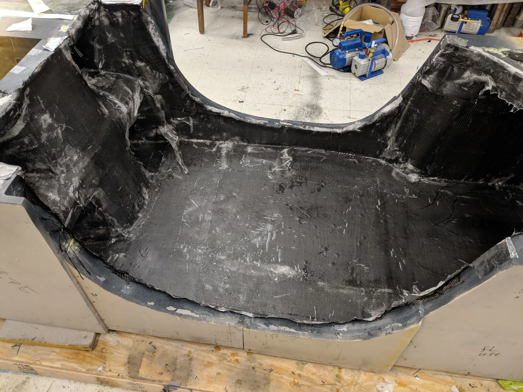
With VARTM being impossible, we ripped off all spiral tubing and infusion mesh to begin wet layup on the carbon fiber and peel ply. This was after testing to ensure the resin will penetrate all 3 layers of carbon fiber and the peel ply.
Wet layup on the hollow rear pillars proved to be extremely difficult. The rear pillars will prove difficult during the entire chassis manufacturing process.
Chassis wet layup complete and curing.
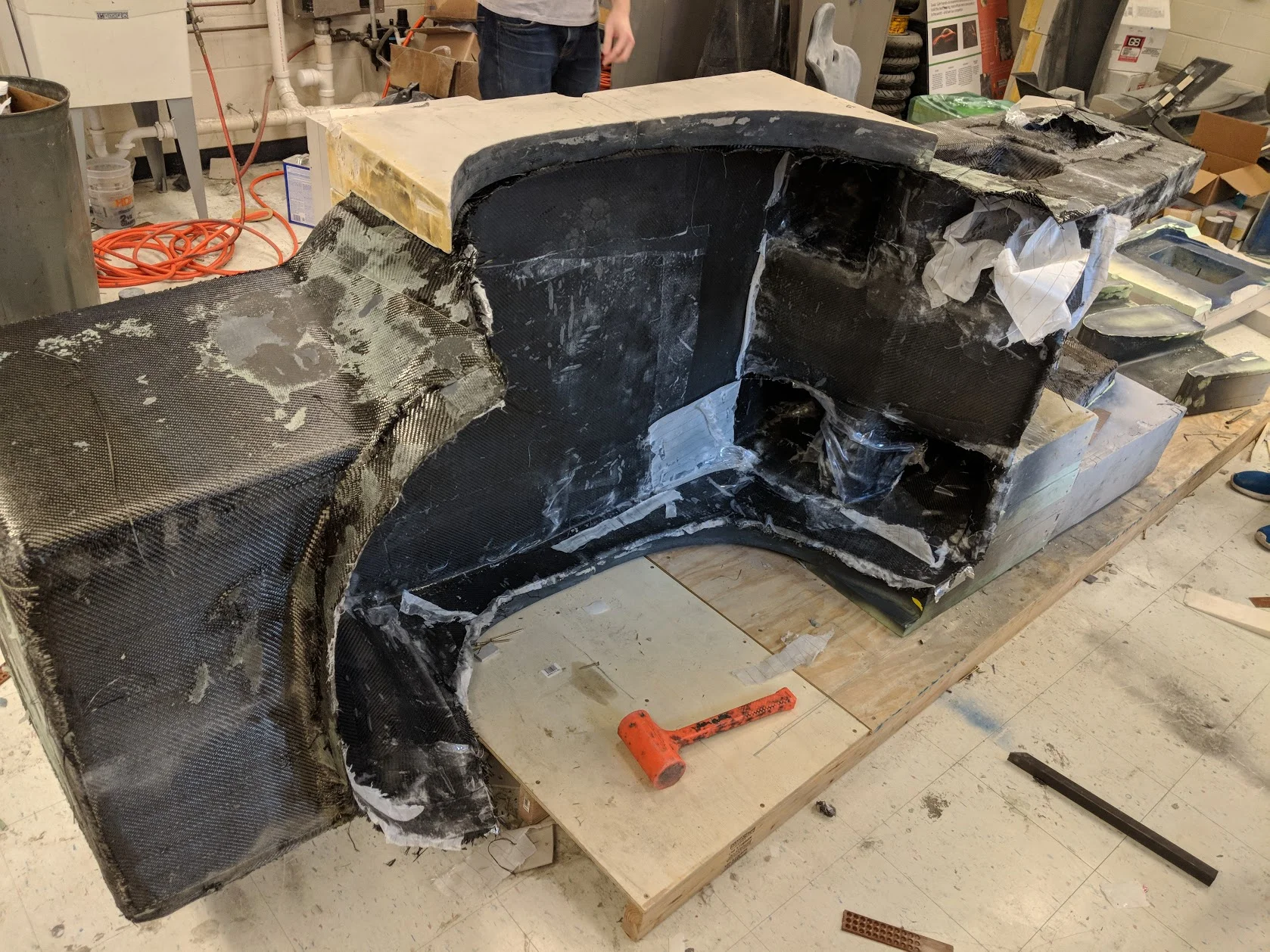
The chassis being de-molded. Mold sub sections were broken out.
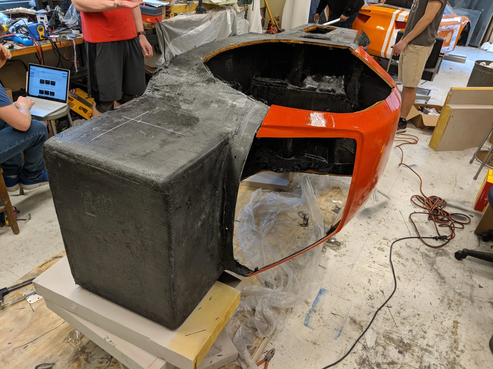
Chassis right after being complete de-molded.
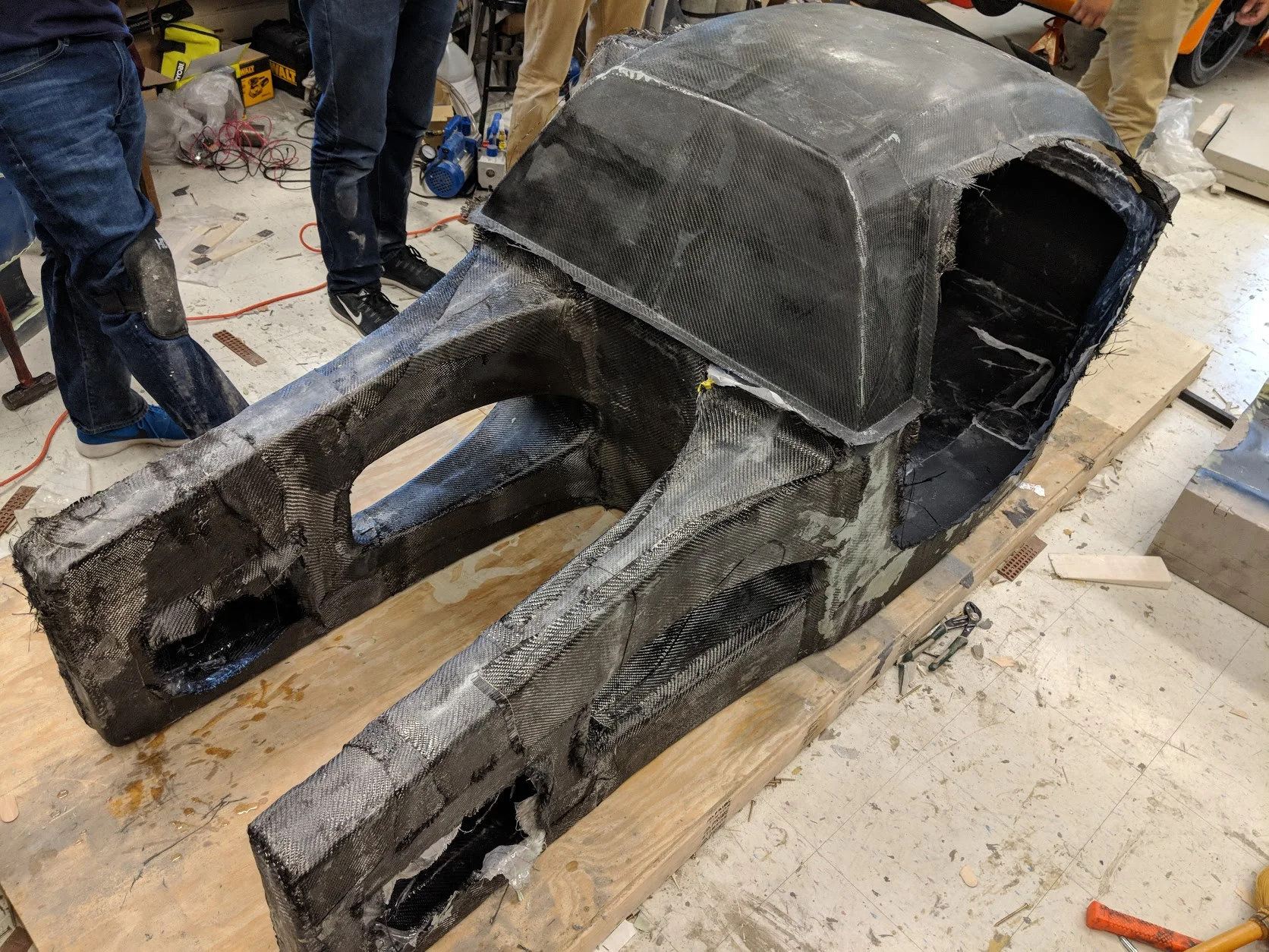
Chassis with the driver inside a temporary assembly of roof and body panels.
Rear view of the chassis with the roof on it.
Chassis after being trimmed, cleaned, and resin pressed into the outer layers that were still without resin.
Nomex core being wet laid into the chassis to increase stiffness and strength.
Top layer of carbon fiber over the Nomex core material.
More chassis reinforcement.
Chassis roof attached and reinforced, with additional reinforcement at the seams between the chassis and the roof.
Chassis with suspension and powertrain attached.