


Goals:
Increased rigidity
Decreased weight
Manufacturable
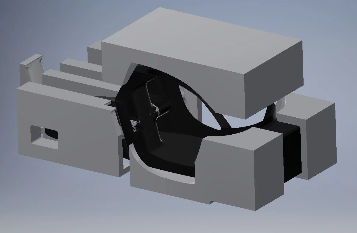
To ensure any team member could drive EV1, I scanned our tallest member, my 6’5” twin brother Robert Mauge. He was scanned using an Xbox Kinect sensor and I placed his 3D scanned model in the chassis model.
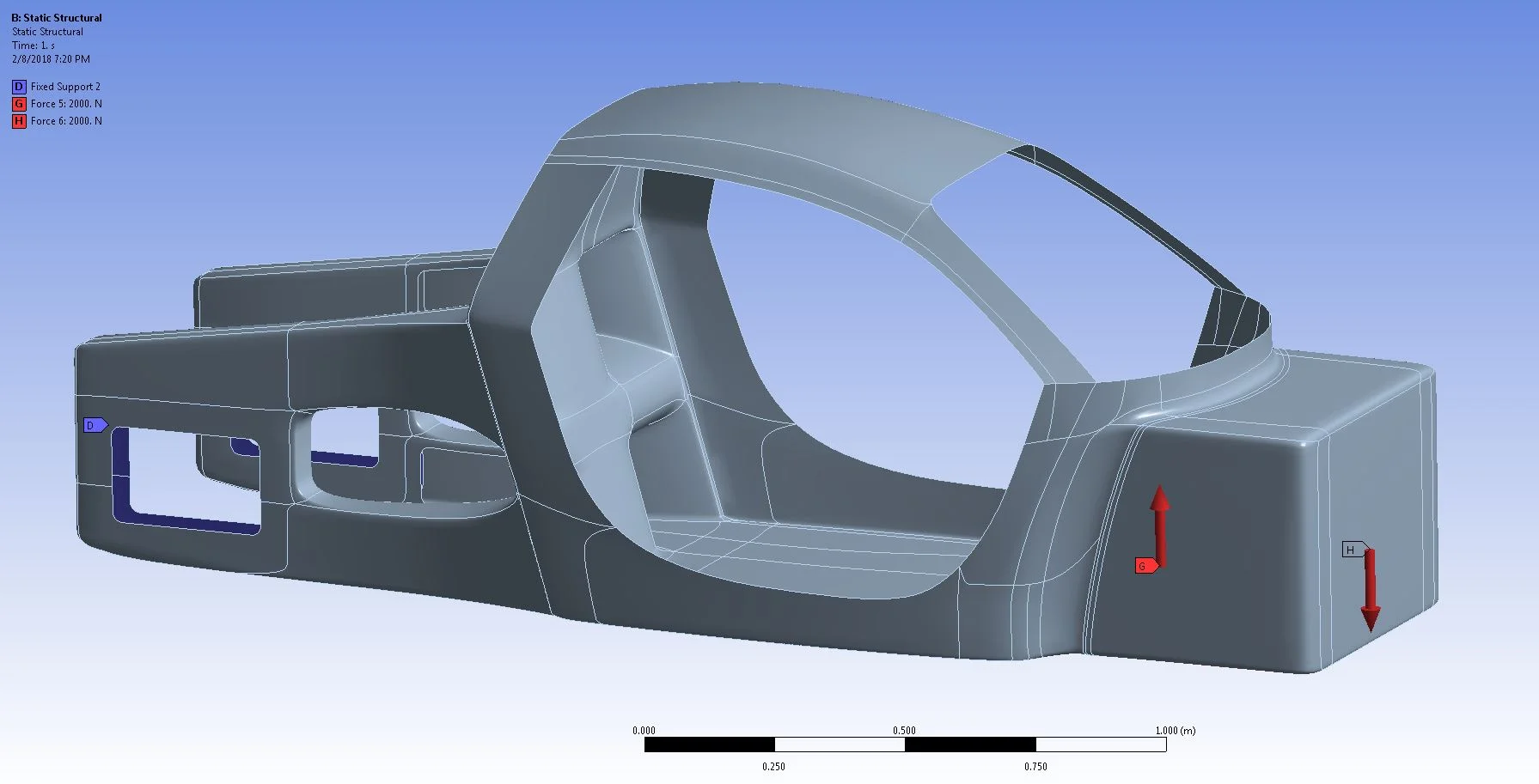
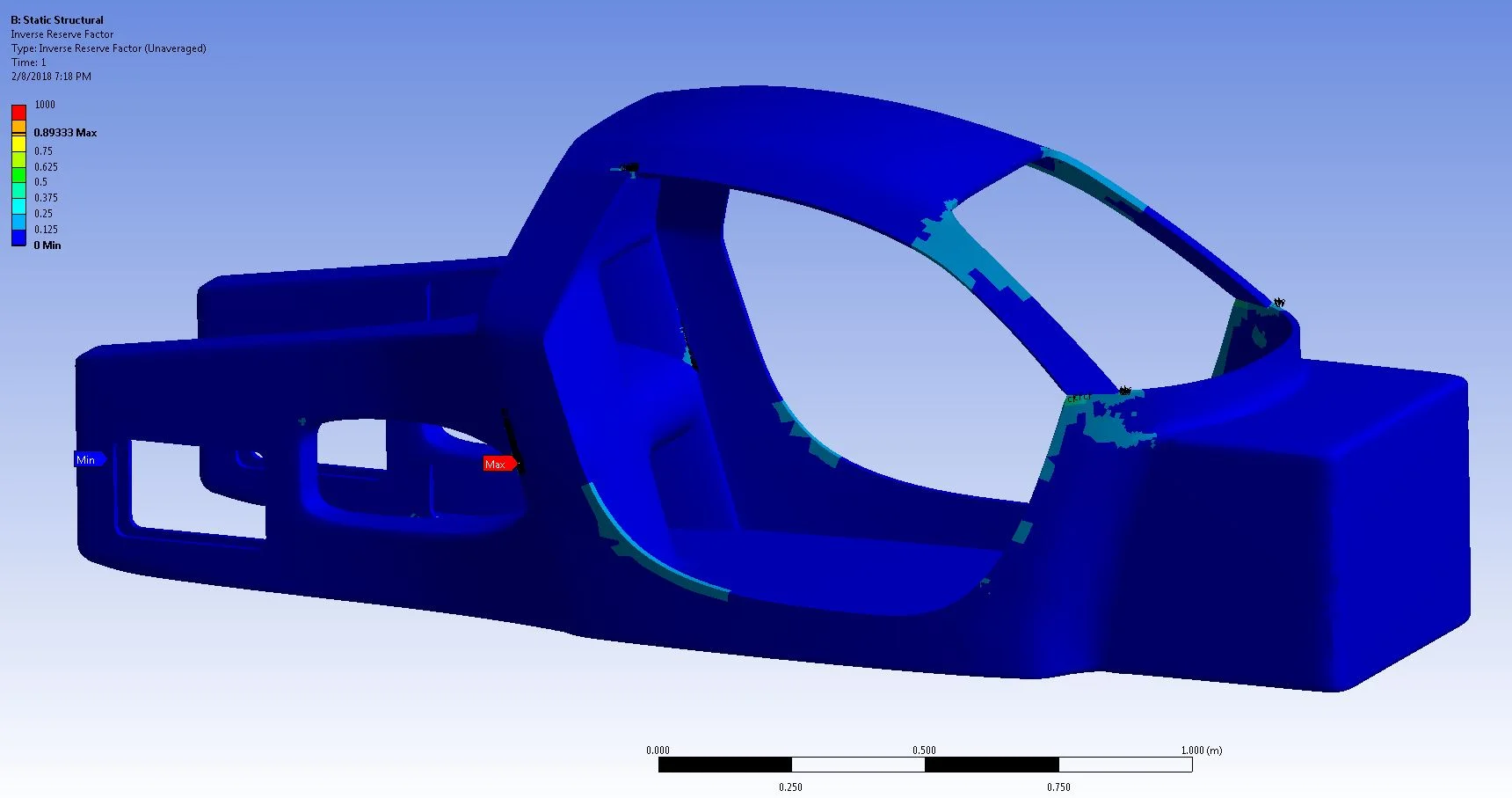
Several FEA tests were performed in ANSYS using the ACP workbench add on to determine the least amount of carbon fiber and core material needed for the most optimal geometry.
The composite failure tool was used to determine if the chassis composite failed under a given condition.
The chassis was intended to be created in one piece, with separate mold sections shown in the following image.